Đọc phim CBCT: lý thuyết và thực hành
A Comprehensive Guide to the Interpretation of Dental Cone Beam Computed Tomography
Part I: Foundational Principles of Cone Beam Computed Tomography
Cone Beam Computed Tomography (CBCT) represents a paradigm shift in maxillofacial imaging, providing clinicians with three-dimensional (3D) volumetric data that overcomes the inherent limitations of two-dimensional (2D) radiography. Its development in the late 1990s by Dr. Yoshinori Arai in Japan and Dr. Piero Mozzo in Italy specifically for oral and maxillofacial applications has since revolutionized diagnosis and treatment planning across all dental specialties.1 A thorough understanding of its underlying physical principles is prerequisite to its effective and responsible clinical use.
1.1 The Physics of CBCT: From Cone Beam to Voxel
The fundamental mechanism of CBCT is distinct from that of conventional medical computed tomography (CT). This distinction is the source of both its primary advantages and its limitations in the dental setting.
Mechanism of Acquisition
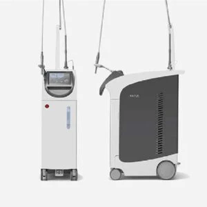
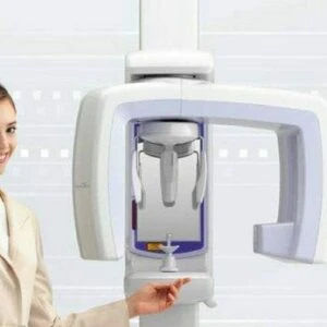
A CBCT scanner utilizes a divergent, cone-shaped X-ray beam directed at a reciprocating, solid-state flat-panel detector.3 The X-ray source and detector are mounted on a gantry that rotates around the patient's head, which is stabilized to prevent motion. In a single rotational scan of 180 to 360 degrees, the system acquires a series of up to 600-1024 individual 2D projection images, often referred to as "basis" images.1 Each basis image is captured from a slightly different angle, similar to a sequence of lateral cephalometric images.3 This single-rotation acquisition of the entire volume of interest contrasts sharply with the slice-by-slice or helical acquisition method of conventional fan-beam CT, which requires multiple gantry rotations to build a volumetric dataset.3
Data Reconstruction and Isotropic Voxels
The raw 2D projection images are instantaneously conveyed to a computer, where a sophisticated mathematical procedure, typically a modified Feldkamp algorithm, reconstructs them into a 3D volumetric dataset.3 This digital volume is composed of three-dimensional pixels known as voxels.1 A defining and critical feature of CBCT is the generation of isotropic voxels, meaning each voxel is a perfect cube with equal dimensions in height, width, and depth.9 This property ensures that the reconstructed images are geometrically accurate and free from distortion, allowing for precise, 1:1 ratio measurements in any plane.3 The isotropic nature of the data permits the entire volume to be reoriented to align with the patient's anatomical features without any loss of spatial resolution or geometric fidelity, a significant advantage over the typically anisotropic (rectangular) voxels produced by medical CT.6
Field of View (FOV)
The dimensions of the scanned anatomical volume are defined by the Field of View (FOV). The size and shape of the FOV are determined by the detector size, beam projection geometry, and the ability to collimate the primary X-ray beam.4 Collimation is a crucial feature that limits radiation exposure strictly to the region of interest, ensuring that an optimal FOV can be selected for each specific diagnostic task.4 CBCT systems are categorized by the available FOV heights 4:
- Localized Region: Approximately 5 cm or less, used for dentoalveolar or temporomandibular joint (TMJ) imaging.
- Single Arch: 5 cm to 7 cm, for imaging the maxilla or mandible.
- Interarch: 7 cm to 10 cm.
- Maxillofacial: 10 cm to 15 cm, extending from the mandible to the nasion.
- Craniofacial: Greater than 15 cm.
Exposure Parameters
During the scan, which can range from 5 to 40 seconds depending on the unit, the X-ray beam may be emitted continuously or, more commonly, in a pulsed fashion.3 Pulsed exposure, where the X-ray beam is activated only to coincide with detector sampling, markedly reduces the total exposure time and, consequently, the patient's radiation dose.4 The typical operating X-ray parameters for CBCT are in the range of 90-120 kilovolt peak (kVp) and 1-15 milliamperes (mA), a range comparable to that of panoramic radiography and considerably lower than that of conventional CT.3
1.2 CBCT vs. Conventional Medical CT: A Comparative Analysis
While both are forms of computed tomography, CBCT and conventional medical CT (often multi-detector CT or MDCT) are designed for different purposes, resulting in significant differences in their performance characteristics.
- Beam Geometry and Acquisition: As established, CBCT uses a cone-shaped beam in a single rotation to capture a volume, whereas conventional CT uses a narrow, fan-shaped beam to acquire individual slices in a helical progression, requiring many rotations.3
- Radiation Dose: The single-rotation acquisition, lower mA settings, and potential for pulsed exposure contribute to CBCT delivering a substantially lower radiation dose to the patient. The total radiation dose from a dental CBCT scan is reported to be up to 15 times lower than that of a conventional maxillofacial CT scan.3 A retrospective study comparing patients who had undergone both modalities for dental applications found that the effective dose from CBCT was significantly lower than from medical CT.11
- Image Quality and Resolution: CBCT is optimized for imaging hard tissues. It provides excellent spatial resolution, with sub-millimeter voxel sizes (as small as 0.075 mm) that are ideal for visualizing the fine details of teeth and bone.2 However, this comes at the cost of inferior low-contrast resolution. Due to higher levels of scatter radiation and limitations of the detector technology, CBCT is poor at differentiating soft tissues, a domain where medical CT and Magnetic Resonance Imaging (MRI) are far superior.5
- Hounsfield Units (HU): In medical CT, the grayscale value of each voxel is standardized to a Hounsfield Unit (HU) scale, which provides an accurate measure of tissue radiodensity. This is not the case with CBCT. Due to the cone-beam geometry, increased scatter, and different reconstruction algorithms, the voxel values in a CBCT scan are not standardized and cannot be reliably interpreted as true HU values for bone density assessment.1
- Cost and Accessibility: CBCT units are significantly smaller, less expensive to purchase and maintain, and better suited for the outpatient dental practice environment compared to the large, costly, and space-intensive medical CT scanners typically found in hospitals.5
1.3 Radiation Dosimetry and the ALARA Principle in Dental Imaging
The use of any ionizing radiation in healthcare requires a careful balancing of diagnostic benefit against potential risk. This is governed by the ALARA (As Low As Reasonably Achievable) principle, which mandates that every effort be made to minimize radiation exposure to patients without compromising diagnostic quality.14
Quantifying and Comparing Radiation Doses
The effective dose, measured in microsieverts ($\mu Sv$) or millisieverts ($mSv$), is the most useful metric for comparing the stochastic risk of radiation from different imaging procedures, as it accounts for the varying sensitivity of different body tissues to radiation.11 Understanding the relative doses of common dental imaging procedures is essential for applying the ALARA principle.
Imaging Procedure Typical Effective Dose (μSv) Equivalent Background Radiation Single Intraoral X-ray 1-8 $\mu Sv$ ~1 day Cephalometric X-ray 2-3 $\mu Sv$ < 1 day Panoramic X-ray 4-30 $\mu Sv$ ~2-3 days CBCT (Small FOV) < 50 $\mu Sv$ ~6 days CBCT (Medium/Large FOV) ~100+ $\mu Sv$ ~12+ days Coast-to-Coast Flight ~80 $\mu Sv$ ~10 days Medical Head CT 1,900-2,700 $\mu Sv$ (1.9-2.7 $mSv$) ~3 years Table 1: A comparison of typical effective radiation doses from various dental imaging modalities and other common sources. Data synthesized from sources.11
As Table 1 illustrates, while CBCT represents a significant dose reduction compared to medical CT, it still delivers a higher dose than conventional 2D dental radiography.1 This reinforces the guideline that CBCT should not be used for routine screening purposes, such as for caries detection or generalized periodontal assessment, where 2D imaging is sufficient.2 The decision to use CBCT must be justified on a case-by-case basis, reserved for clinical situations where the unique 3D information it provides is expected to alter the diagnosis or treatment plan in a way that benefits the patient.7 The selection of an imaging modality is not merely a matter of choosing the lowest dose but rather of optimizing the dose-to-information ratio for a specific clinical question. The technical factors that allow CBCT to achieve a lower dose than medical CT—such as lower mA settings and a single-rotation cone beam—are the very same factors that result in its primary limitations: higher image noise, increased scatter, and poor soft-tissue contrast.3 An expert clinician, therefore, does not simply order a "CBCT." They first precisely define the diagnostic information required. If the question pertains to the 3D position of an impacted tooth relative to the mandibular canal, a limited FOV CBCT provides the necessary information at the lowest appropriate dose. If, however, the question involves the potential invasion of a lesion into adjacent soft tissue compartments, the poor low-contrast resolution of CBCT makes it an inadequate tool, and a higher-dose medical CT or a non-ionizing MRI would be the more appropriate choice. This nuanced decision-making process represents a sophisticated application of the ALARA principle, ensuring that the radiation dose is not just low, but reasonably and justifiably matched to the diagnostic yield required for optimal patient care. ________________
Part II: A Systematic Protocol for CBCT Interpretation
The transition from viewing 2D radiographs to interpreting 3D volumetric datasets requires a disciplined and structured approach. A systematic protocol is essential to ensure a thorough and accurate evaluation, prevent diagnostic errors, and fulfill the clinician's medico-legal responsibilities.
2.1 Orienting the Data: Mastering the Axial, Coronal, and Sagittal Planes
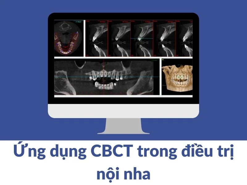
The raw data from a CBCT scan is a volumetric block of isotropic voxels. To interpret this data, it must be visualized as a series of 2D slices in three orthogonal (mutually perpendicular) planes.3
- Axial Plane: Provides a "top-down" view, as if slicing horizontally through the head.
- Coronal Plane: Provides a "front-to-back" view, as if slicing vertically from ear to ear.
- Sagittal Plane: Provides a "side" view, as if slicing vertically from front to back through the midline or parasagittally.
This process of creating 2D images from the 3D volume is known as Multiplanar Reformation (MPR).3 Because the voxels are isotropic, the software can also generate non-orthogonal (oblique) slices and curved planar reformations, which are used to create familiar panoramic-like views.3 The first and most critical step in interpretation is to reorient the data into a standardized anatomical position.16 This ensures that views are consistent and that measurements are accurate. The standard protocol is as follows 16: 1. In the axial view, adjust the volume so that the maxilla and mandible display bilateral symmetry. 2. In the sagittal and coronal views, adjust the volume so that the occlusal plane is oriented parallel to the virtual floor of the display. Once oriented, the image display should be optimized by adjusting the brightness and contrast (a process known as "windowing" or "window leveling") and sharpness to enhance the visibility of specific structures, such as bone versus soft tissue.14
2.2 The Global-to-Focal Review: A Step-by-Step Methodological Approach
To avoid confirmation bias—the tendency to focus only on the area of initial interest—a global-to-focal review strategy is mandatory. This involves a systematic exploration of the entire dataset before focusing on the specific region for which the scan was prescribed. The recommended exploration method is to scroll through the entire volume, slice by slice, in at least two of the orthogonal planes.16 For example, one might scroll from superior to inferior (craniocaudally) through the axial slices, and then repeat the process from anterior to posterior through the coronal slices. This disciplined "march" through the data ensures that no anatomical region is overlooked.14 A structured review should follow a consistent anatomical checklist: 1. Global Overview/Extragnathic Structures: Begin by examining the periphery of the scan volume. Assess the visible portions of the paranasal sinuses, the airway, the temporomandibular joints, and the cervical spine (if included in the FOV). 2. Jaws (Maxilla and Mandible): Evaluate the overall architecture of the maxilla and mandible. Trace the cortical borders, assess the trabecular bone pattern, and examine the integrity of key structures like the floor of the maxillary sinus and the mandibular canal. 3. Dentition: Systematically evaluate each tooth. Note the presence, absence, or impaction of teeth. Examine the coronal structures for caries or restorations, and the roots for morphology, fractures, or resorption. Assess the periapical and periodontal status of each tooth. 4. Region of Interest (ROI): Finally, perform a detailed, multiplanar analysis of the specific anatomical area or clinical problem that prompted the scan.
2.3 The Mandate to Review the Entire Volume: Identifying Incidental Findings
A fundamental principle of CBCT interpretation is the medico-legal responsibility of the prescribing clinician to review and report on the entire data volume acquired, not just the primary ROI.21 This responsibility arises from the high prevalence of incidental findings—pathological or anomalous findings that are unrelated to the original reason for the scan. Studies have shown the prevalence of incidental findings in CBCT scans to be remarkably high, ranging from 17% to as high as 93%.21 One comprehensive review of 100 consecutive scans found that 100% of patients had at least one incidental finding, with 49.1% of these findings requiring clinical intervention.24 These findings are most often discovered in extragnathic regions outside the immediate dentoalveolar complex, such as 21:
- Paranasal Sinuses: Mucosal thickening, sinus opacification, retention pseudocysts, and sinusitis.
- Airway: Constrictions or asymmetries.
- Temporomandibular Joints: Degenerative changes, osteophytes.
- Soft Tissues: Calcifications of the tonsils (tonsilloliths), carotid arteries, or lymph nodes.
- Cervical Spine: Degenerative changes or anomalies (if included in a large FOV).
Failure to identify, document, and appropriately refer a patient for a significant incidental finding can lead to delayed diagnosis of a potentially serious condition, resulting in patient harm and constituting a breach of the standard of care with severe medico-legal consequences.21 The act of prescribing a CBCT scan fundamentally expands the clinician's diagnostic responsibility from a localized dental issue to the entire maxillofacial region captured within the selected FOV. This expansion creates a potential "competency gap," as many dentists have not received adequate postgraduate training in the interpretation of the full spectrum of craniofacial anatomy and pathology visible on these scans.21 This gap between legal responsibility and clinical expertise introduces a significant risk. Consequently, the safe and ethical integration of CBCT into dental practice cannot be treated as simply acquiring a "better periapical." It necessitates a fundamental shift in clinical workflow. This evolution points toward two parallel paths: either the establishment of mandatory advanced training in maxillofacial radiology for all clinicians who utilize CBCT, or, more practically, a greater reliance on formal interpretation by board-certified oral and maxillofacial radiologists. This fosters a necessary and collaborative relationship, mirroring the model in medicine where generalists and specialists consult with radiologists. The CBCT scan thus becomes more than just an in-office diagnostic tool; it serves as a catalyst for interdisciplinary consultation, ultimately elevating the standard of care and redefining the scope of diagnostic practice in modern dentistry. ________________
Part III: Radiographic Anatomy of the Maxillofacial Region
Accurate interpretation of CBCT scans requires a comprehensive understanding of the normal radiographic appearance of the complex anatomy of the maxillofacial region. This serves as the baseline against which pathology is detected.
3.1 The Dentition and Supporting Structures
CBCT provides an unparalleled view of the teeth and their supporting apparatus.
- Dental Tissues: The distinct radiodensities of dental tissues are clearly visible. Enamel, being the most mineralized tissue, appears highly radiopaque (bright white). Dentin is slightly less radiopaque, appearing as a darker shade of gray beneath the enamel. The pulp chamber and root canals, containing soft tissue, are radiolucent (dark).26
- Periodontium: The structures of the periodontium are visualized with high precision. The periodontal ligament (PDL) space appears as a thin, uniform radiolucent line surrounding the entirety of the tooth root. The lamina dura, the cortical bone lining the tooth socket, is visible as a corresponding thin, continuous radiopaque line immediately adjacent to the PDL space.26 The integrity and uniform thickness of these structures are key indicators of periodontal health.
3.2 The Maxilla and Mandible: Key Landmarks and Canals
The jawbones form the primary framework of the lower face, housing the dentition and numerous critical neurovascular structures.
The Maxilla
The maxilla forms the upper jaw and contributes to the hard palate, the floor of the orbit, and the lateral walls of the nasal cavity. Key landmarks visible on CBCT include 26:
- Alveolar Process: The portion of the maxilla that supports the teeth. Its cortical plates and internal trabecular bone pattern are well-defined.
- Infraorbital Foramen: Located inferior to the orbit, transmitting the infraorbital nerve and vessels.
- Nasopalatine Canal (Incisive Canal): A radiolucent channel in the anterior midline of the maxilla, posterior to the central incisors, housing the nasopalatine nerve and vessels.
The Mandible
The mandible, or lower jaw, is a U-shaped bone that articulates with the skull base at the TMJs. Important landmarks include 26:
- Condyle: The superior aspect of the ramus that articulates with the glenoid fossa of the temporal bone.
- Ramus: The vertical portion of the mandible.
- Mental Foramen: An opening on the buccal surface, typically located near the apices of the premolars, through which the mental nerve and vessels exit. It appears as a distinct break in the buccal cortical plate.9
- Genial Tubercles: Bony prominences on the lingual aspect of the anterior mandible that serve as muscle attachments.
Inferior Alveolar Canal (Mandibular Canal)
This is arguably the most critical anatomical structure within the mandible for dental procedures. On CBCT, the mandibular canal appears as a well-defined, tube-like radiolucent pathway, often outlined by a thin, radiopaque cortical border representing the wall of the canal.9 It can be traced from its origin at the mandibular foramen on the medial aspect of the ramus, coursing anteriorly through the body of the mandible, and terminating at the mental foramen.9 Its precise 3D location relative to tooth roots and potential implant sites is a primary indication for CBCT in oral surgery and implantology.
3.3 The Paranasal Sinuses and Nasal Cavity
The air-filled spaces of the sinuses and nasal cavity are prominent features in most maxillofacial CBCT scans.
- Maxillary Sinus: This is the largest of the paranasal sinuses, appearing as a large, pyramidal-shaped radiolucent (air-filled) cavity within the body of the maxilla.18 In a healthy state, its bony walls should appear thin and intact, and the mucosal lining should be either invisible or seen as a very thin, smooth layer. The ostium, the natural drainage opening into the nasal cavity, may also be visualized. Bony partitions, known as sinus septa, are common normal variants.26
- Nasal Cavity: The nasal cavity is divided by the nasal septum. A deviated septum is a frequent anatomical variation and not necessarily pathological.18 Projecting from the lateral walls are the curved bony structures of the nasal conchae (turbinates). A common variant is the pneumatization (air-filling) of the middle turbinate, known as a concha bullosa, which can sometimes obstruct sinus drainage.16
3.4 The Temporomandibular Joints (TMJ)
CBCT is excellent for evaluating the osseous components of the TMJ. Key features include 26:
- Mandibular Condyle: The head of the condyle should have a smooth, rounded, and uniform cortical outline.
- Glenoid Fossa: The corresponding depression in the temporal bone where the condyle articulates.
- Articular Eminence: The bony prominence anterior to the glenoid fossa that guides condylar movement during jaw opening.
________________
Part IV: Radiographic Manifestations of Dental and Jaw Pathologies
With a firm grasp of normal anatomy, the clinician can begin to identify deviations that signify pathology. CBCT's 3D capabilities provide unique insights into the nature, extent, and characteristics of various disease processes.
4.1 Endodontic Lesions: Differentiating Periapical Cysts, Granulomas, and Abscesses
Inflammatory lesions of pulpal origin are among the most common pathologies identified. CBCT has proven to be significantly more sensitive than 2D radiography for their detection, especially for lesions that have not yet perforated the cortical bone.27 These lesions manifest as radiolucencies in the periapical bone, representing localized resorption caused by infection spreading from the root canal system.28 The differentiation between a periapical granuloma and a radicular cyst is a classic diagnostic challenge with important treatment implications, as true cysts may be less likely to resolve with non-surgical root canal therapy alone.30 While histopathology remains the definitive gold standard, CBCT provides features that strongly favor one diagnosis over the other.31
- Periapical Granuloma: This is a mass of solid, chronic inflammatory tissue. On CBCT, granulomas are often described as having less-defined, diffuse, or non-corticated borders.14 They may be smaller in volume compared to cysts.30 Some studies using grayscale value analysis have suggested that granulomas, being solid tissue, have a narrower range of positive grayscale values compared to the fluid-filled nature of cysts.33
- Radicular Cyst: This is a true pathologic cavity lined by epithelium and typically filled with fluid or semi-solid material.30 Radiographically, cysts tend to present as well-defined, unilocular radiolucencies with a distinct corticated border.14 They are more likely to be larger and cause expansion or thinning of the buccal and/or lingual cortical plates due to hydrostatic pressure.30 Grayscale analysis may reveal negative values within the lesion, corresponding to its fluid content.33
- Odontogenic Sinusitis: Periapical infection of the maxillary posterior teeth can readily spread into the overlying maxillary sinus, causing an inflammatory reaction of the sinus mucosa (Schneiderian membrane). This is a common cause of maxillary sinusitis, accounting for an estimated 10-12% of cases.36 On CBCT, this is visualized as localized sinus mucosal thickening (SMT) adjacent to the apex of the offending tooth.27 CBCT is the ideal modality for demonstrating this direct causal relationship, which is often ambiguous on 2D films.
4.2 Periodontal Disease: Assessing Infrabony Defects, Furcation Involvement, and Bone Loss
CBCT overcomes the primary limitation of conventional radiography in periodontics—the inability to visualize the buccolingual dimension of the alveolar bone.7 It provides a true 3D assessment of periodontal bone architecture.
- Infrabony Defect Morphology: The success of periodontal regenerative procedures is highly dependent on the morphology of the bone defect.38 CBCT allows for the accurate classification of infrabony defects based on the number of remaining bony walls:
- Three-wall defect: Has the best regenerative potential.
- Two-wall defect (crater): The most common type of defect.
- One-wall defect: Has the poorest prognosis for regeneration.
CBCT measurements of defect depth and width have shown a high degree of agreement with the gold standard of direct intrasurgical measurements, making it a valid tool for pre-surgical planning.38
- Furcation Involvement: The involvement of the furcation area of multi-rooted teeth is often difficult to diagnose definitively with 2D radiographs due to the superimposition of roots and bone. CBCT provides an unobstructed view, allowing for precise detection and classification of furcation involvement, which is critical for treatment planning and prognosis.39
- Clinical Justification: Despite its diagnostic accuracy, the routine use of CBCT for periodontal diagnosis is not currently recommended due to the increased radiation dose compared to a full-mouth series of periapical and bitewing radiographs.40 Its use should be reserved for specific, complex cases, such as in patients with aggressive periodontitis or for planning complex regenerative or resective surgeries where 2D imaging provides insufficient information.37
4.3 Odontogenic Cysts and Tumors: Radiographic Features and Differential Diagnosis
CBCT is an invaluable tool for the evaluation of intraosseous lesions of the jaws. A systematic analysis of key radiographic features is essential for formulating an accurate differential diagnosis. The evaluation should include 41:
- Location: Anatomic position within the maxilla or mandible.
- Periphery and Shape: Margins can be well-defined, corticated, corticated with scalloping, or ill-defined and invasive.
- Internal Structure: Can be completely radiolucent (cystic), radiopaque (calcified), or mixed density. It can also be unilocular (single cavity) or multilocular (multiple, septated cavities).
- Effect on Surrounding Structures: Evidence of tooth displacement, root resorption, expansion or perforation of cortical plates, and relationship to vital structures like the mandibular canal.
The radiographic appearance of jaw lesions can be highly variable and features often overlap between different entities. A structured approach, comparing the observed features against the typical patterns of common lesions, is crucial for developing a sound differential diagnosis. This process forces the clinician to systematically evaluate specific characteristics—such as locularity, border definition, or the presence of root resorption—rather than relying on a general impression. This structured comparison is an invaluable cognitive aid.
Lesion Typical Location Periphery/Shape Internal Structure Effect on Adjacent Structures Radicular Cyst Apex of a non-vital tooth Well-defined, corticated, round/oval Unilocular, radiolucent May cause tooth displacement and cortical expansion if large 35 Dentigerous Cyst Pericoronal to an unerupted tooth (esp. 3rd molars, canines) Well-defined, corticated, unilocular Unilocular, radiolucent Displaces the associated unerupted tooth; can cause significant expansion 35 Odontogenic Keratocyst (OKC) Posterior mandible/ramus Well-defined, corticated, often with scalloped borders Can be unilocular or multilocular; radiolucent Tends to grow along the bone with minimal expansion; high recurrence rate 42 Ameloblastoma Posterior mandible Well-defined, corticated Multilocular ("soap-bubble" or "honeycomb"), radiolucent Causes significant bone expansion and root resorption; locally aggressive 43 Table 2: A summary of key radiographic features to aid in the differential diagnosis of common odontogenic cysts and tumors on CBCT. Data synthesized from sources.35
One of the most important determinations is whether a lesion exhibits aggressive or non-aggressive behavior. Features suggesting a more aggressive process include ill-defined or invasive borders and, most significantly, perforation of the cortical bone.41 Conversely, a well-defined, corticated border suggests a slower-growing, less aggressive lesion. ________________
Part V: Clinical Applications Across Dental Specialties
The theoretical advantages of CBCT translate into tangible clinical benefits across all disciplines of dentistry, enabling more accurate diagnoses and predictable treatment outcomes.
5.1 Implant Dentistry
CBCT has become the standard of care for pre-surgical implant planning.
- Quantitative and Qualitative Bone Assessment: CBCT provides precise, 1:1 scale measurements of the available bone, particularly the critical buccolingual width, which cannot be assessed with 2D imaging.7 It also allows for the evaluation of ridge morphology (e.g., undercuts, knife-edge ridges) and a qualitative assessment of bone density, which influences treatment planning and surgical approach.44
- Anatomical Structure Localization: It is essential for visualizing the exact 3D course of the mandibular canal, the position of the mental foramen, and the floor and walls of the maxillary sinus.7 This allows the surgeon to plan implant placement that maintains a safe distance from these vital structures, minimizing the risk of neurovascular injury or sinus perforation.45
- Prosthetically Driven, Computer-Guided Surgery: The digital workflow in modern implantology begins with a CBCT scan. The DICOM data is imported into specialized planning software, where a virtual implant can be placed in the ideal position to support the final planned restoration. This virtual plan can then be used to design and 3D-print a surgical guide. The guide fits precisely over the patient's teeth or tissues and directs the surgical drills, allowing for extremely accurate and predictable transfer of the virtual plan to the clinical reality.44 This approach can facilitate flapless surgery, reducing patient morbidity and recovery time.46
5.2 Endodontics
CBCT, particularly with a limited FOV for high resolution and low dose, is a powerful problem-solving tool in endodontics.
- Diagnosis of Persistent Infections: When a patient has persistent symptoms after root canal treatment, CBCT is invaluable for identifying the etiology. It can reveal complex anatomy such as missed or untreated canals (e.g., the second mesiobuccal canal (MB2) of maxillary molars), which are a common cause of endodontic failure.14
- Assessment of Periapical Pathology: As previously discussed, CBCT is superior to 2D radiographs for detecting the presence and true 3D extent of periapical lesions, which can influence the decision between non-surgical retreatment and surgical intervention.14
- Diagnosis of Non-Endodontic Pathologies: It aids in the differential diagnosis of radiolucencies that may mimic endodontic lesions, and can help identify conditions such as vertical root fractures, perforations, and internal or external resorption, which have different treatment protocols and prognoses.14
- Pre-Surgical Planning (Apicoectomy): Before performing apical surgery, a CBCT scan provides the surgeon with a precise 3D map of the root apex's location relative to the cortical plates and adjacent vital structures, allowing for safer and more efficient surgical access.28
5.3 Orthodontics
CBCT provides comprehensive 3D information that is not available from traditional 2D cephalometric and panoramic radiographs.
- Localization of Impacted and Supernumerary Teeth: This is one of the most common and justified indications for CBCT in orthodontics.17 It allows for the precise 3D localization of impacted teeth, particularly maxillary canines, and their relationship to the roots of adjacent teeth.17 Critically, it can detect root resorption on adjacent incisors caused by the impacted tooth, a finding that is frequently missed on 2D films and can dramatically alter the treatment plan.17
- Skeletal and Craniofacial Assessment: CBCT allows for 3D cephalometric analysis, providing a true, non-magnified, and non-distorted view of the skeletal structures.17 It is particularly valuable for the diagnosis and treatment planning of patients with significant facial asymmetry, craniofacial anomalies, and cleft palate.17
- Airway Analysis: The pharyngeal airway can be segmented and its volume and minimum cross-sectional area can be measured from a CBCT scan. This has applications in the orthodontic assessment of patients with potential obstructive sleep apnea.26
- Temporary Anchorage Devices (TADs): For the placement of orthodontic mini-implants, CBCT can be used to assess the thickness of the cortical bone and the proximity of tooth roots at potential placement sites, thereby increasing the success rate and safety of TAD placement.17
5.4 Oral and Maxillofacial Surgery
CBCT is an essential imaging modality in oral and maxillofacial surgery for diagnosis, treatment planning, and post-operative assessment.
- Impacted Third Molar Surgery: For high-risk cases, CBCT is used to precisely evaluate the 3D relationship between the roots of impacted mandibular third molars and the mandibular canal, allowing the surgeon to better assess the risk of inferior alveolar nerve injury and plan the surgical approach accordingly.3
- Maxillofacial Trauma: CBCT is highly sensitive and accurate for the diagnosis of facial bone fractures. It is superior to 2D imaging for identifying non-displaced or minimally displaced fractures, particularly of the mandible and midface, and for assessing the degree of displacement of fracture segments.44
- Pathology and Reconstructive Surgery: For the surgical management of cysts, tumors, and other osseous pathologies, CBCT is indispensable for defining the exact 3D extent of the lesion, its effect on adjacent structures, and the volume of the resulting defect. This information is critical for planning the surgical resection and any subsequent bone grafting or reconstruction.42
________________
Part VI: Understanding and Mitigating CBCT Artifacts
Despite its numerous advantages, CBCT imaging is susceptible to a variety of artifacts that can degrade image quality and potentially lead to misdiagnosis. An artifact is any systematic discrepancy between the reconstructed image and the true physical object, resulting in the obscuring of details or the appearance of structures that do not actually exist.47
6.1 A Taxonomy of Artifacts: Beam Hardening, Scatter, Motion, and Metal Artifacts
Understanding the physical origins of common artifacts is the first step toward recognizing and mitigating them.
- Beam Hardening: This is one of the most prominent artifacts in CBCT.47 The X-ray beam produced by the scanner is polychromatic, meaning it contains photons of varying energy levels. As the beam passes through an object, especially dense materials like enamel or metal, the lower-energy ("softer") photons are absorbed more readily than the higher-energy ("harder") photons. This causes the mean energy of the beam to increase, or "harden".47 Since the reconstruction algorithm assumes a monochromatic beam, this physical phenomenon introduces errors that manifest in two primary ways 47:
1. Cupping Artifact: A characteristic dish-shaped or "cupped" appearance in the image of a uniform dense object, where the center appears artificially darker (less dense) than the periphery. 2. Streaks and Dark Bands: Dark streaks or bands that appear between two dense objects in the image, such as between two metallic restorations or implants.13
- Scatter: Compton scattering occurs when X-ray photons are deflected from their original path upon interacting with the patient's tissues.13 In CBCT, the wide, cone-shaped beam and large area detector result in a significant amount of scattered radiation reaching the detector. This scatter degrades image quality by reducing contrast, increasing noise, and contributing to cupping artifacts.13
- Motion Artifacts: Patient movement during the scan is a significant source of image degradation. Because the reconstruction process assumes a static object, any movement causes a misregistration of the projection data. This results in characteristic artifacts such as blurring, loss of sharpness, and the appearance of double contours or "ghost images".13 Due to the high spatial resolution of CBCT (voxel sizes from 0.08 mm to 0.4 mm), even very small movements can have a detrimental effect on image quality.13
- Metal Artifacts: The presence of highly attenuating materials, such as amalgam restorations, crowns, implants, or orthodontic brackets, causes the most severe artifacts. These materials can absorb almost the entire X-ray beam, leading to a lack of data in their "shadow" on the detector. The reconstruction algorithm attempts to compensate for this missing information, resulting in severe bright and dark streaks that radiate from the metallic object in all directions, often completely obscuring the surrounding anatomy and rendering it diagnostically unusable.13
6.2 The Diagnostic Impact of Image Degradation
Artifacts are not merely aesthetic imperfections; they have direct clinical consequences.
- Obscuring Pathology: Streaking from a metallic crown can completely hide a periapical lesion or a root fracture on the adjacent tooth.
- Simulating Pathology: This is a more insidious problem. Dark bands from beam hardening can be misinterpreted as fracture lines. Cupping artifacts can mimic osteolytic lesions. Ring artifacts, caused by a miscalibrated detector element, can simulate pathology.47 It is therefore imperative that the interpreting clinician be adept at recognizing the characteristic patterns of artifacts to avoid misdiagnosis.
6.3 Clinical and Software-Based Artifact Reduction Strategies
A combination of careful technique during acquisition and the use of advanced software algorithms can help minimize the impact of artifacts.
Artifact Appearance Cause Mitigation Strategies Beam Hardening Cupping (dark center of dense objects); dark streaks between two dense objects. Preferential absorption of low-energy photons in a polychromatic X-ray beam. Software: Use of beam hardening correction algorithms. Technique: Increase kVp to increase beam penetration. Motion Blurring, loss of sharpness, double contours ("ghosting"). Patient movement during the scan acquisition. Technique: Use appropriate head stabilization (chin rest, straps). Instruct the patient to remain perfectly still and avoid swallowing during the scan.13 Metal Streaks Severe bright and dark streaks radiating from metallic objects. Extreme X-ray attenuation by high-density materials (e.g., amalgam, crowns, implants). Software: Employ Metal Artifact Reduction (MAR) algorithms.50 Technique: Use the "puffed-cheek" technique for anterior teeth to create an air gap between the metal and soft tissue, which can reduce streaks.49 Remove any removable metal objects (e.g., jewelry, dentures) before scanning.47 Table 3: A practical guide to the appearance, cause, and mitigation of common CBCT artifacts. Data synthesized from sources.13
Modern CBCT systems increasingly rely on sophisticated software solutions. Metal Artifact Reduction (MAR) algorithms are specifically designed to identify the corrupted data caused by metallic objects and use mathematical interpolation or modeling to "fill in" the missing information, significantly reducing streaks.51 More advanced iterative reconstruction techniques, which are computationally intensive, can model the physics of the imaging process more accurately. They can produce images with substantially reduced noise and artifacts, often while simultaneously allowing for a reduction in the initial radiation dose.50 ________________
Part VII: The Digital Workflow: DICOM Viewers and Radiological Reporting
The final stage of the CBCT process involves interacting with the digital data and communicating the diagnostic findings in a formal, structured manner.
7.1 Navigating the Volumetric Data: Essential Features of DICOM Software
The output of a CBCT scanner is a set of files in the DICOM (Digital Imaging and Communications in Medicine) format. DICOM is the universal standard for storing, transmitting, and viewing medical images.3 A DICOM file is more than just a picture; it is a complex data object that contains a header with patient demographic information, acquisition parameters (e.g., kVp, mA, FOV), and the image pixel data itself.55 This standardization ensures interoperability, allowing images from one manufacturer's scanner to be viewed on another's software.55 Specialized DICOM viewing software is required to interpret these files. While features vary between manufacturers and third-party providers (e.g., Planmeca Romexis, Carestream CS 3D Imaging, MicroDicom, RadiAnt), a robust viewer should include the following essential tools 56:
- Basic Image Manipulation: Tools for fluid zooming and panning, rotating/flipping images, and adjusting brightness and contrast (window/level) are fundamental.56
- Multi-Planar Reconstruction (MPR): The core function of any 3D viewer is the ability to display and synchronously scroll through the axial, coronal, and sagittal planes. The software should also allow for the creation of oblique and curved planar reformations to generate panoramic and cross-sectional views.56
- 3D Volume Rendering: This feature creates a photorealistic 3D model of the scanned anatomy, which is invaluable for visualizing spatial relationships, planning surgery, and educating patients.58
- Measurement and Annotation: The ability to perform accurate linear, angular, and area/volume measurements is critical for quantitative analysis. Annotation tools allow the user to add text, arrows, or other markers directly onto the images to highlight findings.56
- Dental-Specific Modules: Many dental DICOM viewers include specialized toolsets for tasks such as tracing the path of the mandibular nerve, planning implant placement with a virtual library of implants, or automatically segmenting anatomical structures like teeth, jaws, and airways using artificial intelligence.58
- PACS/VNA Integration: For larger clinics or hospital settings, the software should be able to communicate with a Picture Archiving and Communication System (PACS) or a Vendor Neutral Archive (VNA). This allows for querying and retrieving patient studies from a central server and storing new scans, creating an integrated enterprise imaging workflow.53
7.2 The Structured Radiological Report: Components and Best Practices
The radiological report is the formal, legal record of the clinician's interpretation of the CBCT scan. Its purpose is to communicate the findings, diagnostic impression, and any recommendations to the referring clinician in a clear, concise, and unambiguous manner.25 Adhering to a structured format ensures completeness and consistency. Based on guidelines from professional bodies like the European Academy of Dental and Maxillofacial Radiology (EADMFR), a comprehensive CBCT report should contain the following key components 25: 1. Patient and Examination Details:
- Patient Information: Full name, date of birth, unique patient identifier.
- Referrer Information: Name and contact details of the referring clinician.
- Examination Information: Date of scan, type of scanner, and acquisition parameters (FOV, voxel size, exposure settings).
2. Clinical Indication: A clear statement of the reason for the examination and the specific clinical question(s) posed by the referrer. 3. Image Quality Assessment: A brief comment on the diagnostic quality of the scan, noting the presence of any significant artifacts (e.g., motion, metal) that may limit interpretation. 4. Findings: This is the main body of the report. It should provide a systematic and objective description of the findings from the global-to-focal review. It is best organized by anatomical region:
- Dentoalveolar Structures: General assessment of the dentition, including missing/unerupted teeth, caries, restorations, and the periapical and periodontal status of all teeth within the FOV.
- Maxilla and Mandible: Assessment of bone quality, alveolar ridge morphology, and any osseous pathology.
- Paranasal Sinuses: Description of the maxillary, ethmoid, and sphenoid sinuses (if visible), noting mucosal health and patency of ostia.
- Nasal Cavity and Airway: Assessment of the nasal septum, turbinates, and the patency of the visualized airway.
- Temporomandibular Joints: Description of the osseous components of the condyles and fossae.
- Other Structures: Note any findings in the cervical spine or soft tissue calcifications if visible.
5. Impression / Conclusion: This section provides a synthesis of the descriptive findings into a concise diagnostic summary. It should directly address the clinical question from the indication. A differential diagnosis, typically listed in order of likelihood, should be provided for any identified pathology. 6. Recommendations: If appropriate, this section may suggest further clinical correlation, referral to another specialist (e.g., ENT, oral surgeon), or the need for follow-up imaging. 7. Reporter Identification: The report must be concluded with the name, qualifications, and signature of the interpreting clinician, along with the date of the report. Best practice dictates that the entire volume must be reviewed and all significant findings, including incidental ones, must be documented in the report.20 ________________
Appendix: Illustrative Case Studies
The following clinical cases demonstrate the practical application of the principles and protocols discussed in this guide, highlighting the diagnostic power of CBCT in real-world scenarios.
Case Study 1: Endodontic Diagnosis of a Missed Canal
- Clinical Presentation: A 50-year-old male patient was referred for persistent pain and percussion sensitivity on a mandibular premolar following root canal treatment by his general dentist. A conventional 2D periapical radiograph showed what appeared to be a well-obturated buccal canal with no obvious signs of periapical pathology.27
- CBCT Acquisition and Findings: A limited FOV CBCT scan was acquired to investigate the cause of the persistent symptoms. The multiplanar reformation revealed a second, untreated canal on the lingual aspect of the root, which was completely obscured on the 2D radiograph due to anatomical superimposition. The axial and coronal views clearly demonstrated the presence of the missed canal and an associated, small, non-corticated periapical radiolucency indicative of chronic apical periodontitis.27
- Diagnostic Impact and Outcome: The CBCT provided a definitive diagnosis that was unattainable with conventional imaging. It identified the precise etiology of the treatment failure—the missed lingual canal. This allowed for a targeted non-surgical retreatment. The lingual canal was located, instrumented, and obturated. The patient's symptoms resolved completely following the procedure. This case exemplifies the crucial role of CBCT in managing complex root canal anatomy and diagnosing persistent endodontic infections.
Case Study 2: CBCT-Guided Implant Placement in the Anterior Mandible
- Clinical Presentation: A 44-year-old female patient with a history of periodontal disease presented with Grade II mobility of her mandibular incisors and desired a fixed implant-supported restoration.45
- CBCT Acquisition and Findings: A maxillofacial CBCT scan was taken for comprehensive treatment planning. The scan confirmed severe horizontal bone loss around the incisors. However, the cross-sectional views revealed adequate residual bone height apical to the teeth and, critically, showed thick buccal and lingual cortical plates with minimal lingual concavity—a favorable anatomy for implant placement. The DICOM data was integrated with a digital scan of a diagnostic wax-up, allowing for prosthetically driven virtual implant planning. The implants were positioned in the software to provide ideal support for a screw-retained bridge while ensuring a safe distance from the lingual cortical plate.45
- Diagnostic Impact and Outcome: The CBCT data was used to fabricate a 3D-printed surgical guide. During surgery, the guide enabled the precise placement of two dental implants according to the virtual plan, with excellent primary stability. This computer-guided approach minimized the need for extensive flap reflection and reduced surgical time. After an 8-week healing period, a definitive screw-retained bridge was delivered, restoring function and aesthetics. This case demonstrates the indispensable role of CBCT in the modern implant workflow, facilitating safe, predictable, and prosthetically driven outcomes.
Case Study 3: Orthodontic Evaluation of an Impacted Canine and Associated Root Resorption
- Clinical Presentation: A 13-year-old patient was referred for orthodontic evaluation due to the clinical absence of the permanent maxillary right canine. A 2D panoramic radiograph confirmed the impaction but provided limited information regarding its exact position and its relationship to adjacent teeth.17
- CBCT Acquisition and Findings: A limited FOV CBCT focused on the anterior maxilla was acquired. The volumetric data provided a clear, 3D visualization of the impacted canine, revealing its precise palatal position and horizontal angulation. More significantly, the high-resolution axial and sagittal slices revealed a large area of external root resorption on the palatal aspect of the adjacent maxillary right lateral incisor root. This critical finding was not apparent on the initial 2D panoramic radiograph due to superimposition.17
- Diagnostic Impact and Outcome: The information from the CBCT fundamentally altered the treatment plan. What was initially considered a routine surgical exposure and orthodontic alignment of the impacted canine became a complex interdisciplinary case. The CBCT data allowed the orthodontist and oral surgeon to understand the full extent of the iatrogenic damage to the incisor, which now had a guarded prognosis. The treatment plan was modified to include not only the surgical exposure of the canine but also endodontic evaluation of the lateral incisor and a revised orthodontic mechanotherapy to minimize further damage during canine alignment. This case highlights how CBCT can reveal clinically significant pathology that is invisible on conventional imaging, thereby preventing treatment complications and leading to more informed and appropriate patient care.
Conclusion
Cone Beam Computed Tomography has irrevocably transformed the diagnostic landscape of dentistry. By providing distortion-free, three-dimensional views of the maxillofacial skeleton, it empowers clinicians to diagnose with greater accuracy, plan treatments with enhanced predictability, and execute procedures with increased safety. Its superiority over 2D imaging is evident in complex cases across all specialties, from locating a missed canal in endodontics to planning the precise trajectory of a dental implant. However, this powerful technology comes with significant responsibilities. The increased radiation dose relative to conventional radiography necessitates strict adherence to the ALARA principle, mandating that CBCT be used judiciously and only when clinically justified. Furthermore, the vast amount of data generated in a single scan places a medico-legal obligation on the clinician to perform a systematic and comprehensive review of the entire volume, identifying not only the primary pathology but also any incidental findings that may impact the patient's overall health. Mastering CBCT, therefore, is a dual endeavor: it requires not only a technical understanding of the physics, anatomy, and pathology but also a commitment to a disciplined, ethical, and thorough interpretive methodology. When used appropriately, CBCT is an indispensable tool that elevates the standard of care and enables clinicians to achieve outcomes previously thought unattainable. Nguồn trích dẫn 1. Cone beam computed tomography – Wikipedia, truy cập vào tháng 10 21, 2025, https://en.wikipedia.org/wiki/Cone_beam_computed_tomography 2. Dental Cone Beam Computed Tomography – StatPearls – NCBI Bookshelf, truy cập vào tháng 10 21, 2025, https://www.ncbi.nlm.nih.gov/books/NBK592390/ 3. Cone beam computed tomography: basics and applications in …, truy cập vào tháng 10 21, 2025, https://pmc.ncbi.nlm.nih.gov/articles/PMC5750833/ 4. What is Cone-Beam CT and How Does it Work? | Pocket Dentistry, truy cập vào tháng 10 21, 2025, https://pocketdentistry.com/what-is-cone-beam-ct-and-how-does-it-work/ 5. Cone-beam CT | Radiology Reference Article | Radiopaedia.org, truy cập vào tháng 10 21, 2025, https://radiopaedia.org/articles/cone-beam-ct-1 6. Clinical Applications of Cone-Beam Computed Tomography in Dental Practice, truy cập vào tháng 10 21, 2025, https://www.cda-adc.ca/jcda/vol-72/issue-1/75.pdf 7. Cone-Beam Computed Tomography (CBCT) Applications in Dentistry, truy cập vào tháng 10 21, 2025, https://assets.ctfassets.net/u2qv1tdtdbbu/6ObF5l661EIuuxAdprqhND/45900544fcaeb2b183d07058f164fcf5/ce531_10-1-21.pdf 8. CBCT anatomical structures | PPTX – Slideshare, truy cập vào tháng 10 21, 2025, https://www.slideshare.net/slideshow/cbct-anatomical-structures/261685800 9. CBCT Images of Anatomic Landmarks in Maxillofacial Region – DergiPark, truy cập vào tháng 10 21, 2025, https://dergipark.org.tr/tr/download/article-file/165448 10. Imaging anatomy of the jaw and dentition with cone beam computed tomography – UA-repository., truy cập vào tháng 10 21, 2025, https://repository.uantwerpen.be/docstore/d:irua:2422 11. Comparing Radiation Doses in CBCT and Medical CT Imaging for Dental Applications, truy cập vào tháng 10 21, 2025, https://pmc.ncbi.nlm.nih.gov/articles/PMC11174323/ 12. Comparison of radiographical characteristics and diagnostic accuracy of intraosseous jaw lesions on panoramic radiographs and CBCT – PMC, truy cập vào tháng 10 21, 2025, https://pmc.ncbi.nlm.nih.gov/articles/PMC7860957/ 13. Common Image Artifacts in Cone Beam CT – aadmrt, truy cập vào tháng 10 21, 2025, http://www.aadmrt.com/article-1—2008.html 14. Guide to Interpreting CBCT Scans in Endodontics – 3Beam | Cutting-edge medical imaging, truy cập vào tháng 10 21, 2025, https://3beam.co.uk/guide-to-interpreting-cbct-scans-in-endodontics/ 15. Radiation doses in dental radiology – FAQs for health professionals | IAEA, truy cập vào tháng 10 21, 2025, https://www.iaea.org/resources/rpop/health-professionals/dentistry/radiation-doses 16. CBCT interpretation for dental implant treatment planning, truy cập vào tháng 10 21, 2025, https://www.creighton.edu/sites/default/files/2022-10/3%20Paneer.pdf 17. Cone-Beam Computed Tomography in Orthodontics – PMC, truy cập vào tháng 10 21, 2025, https://pmc.ncbi.nlm.nih.gov/articles/PMC6784482/ 18. Anatomy of the Maxillofacial Region in the Three Planes of Section – CBCT Systems | Encompass Dental Solutions, truy cập vào tháng 10 21, 2025, https://cbctsystems.com/wp-content/uploads/2024/05/Anatomy-of-the-Maxillofacial-Region.pdf 19. (PDF) Guidelines and template for reporting on CBCT scans, truy cập vào tháng 10 21, 2025, https://www.researchgate.net/publication/338518577_Guidelines_and_template_for_reporting_on_CBCT_scans 20. Guidelines for reporting on CBCT scans – British Endodontic Society, truy cập vào tháng 10 21, 2025, https://britishendodonticsociety.org.uk/_userfiles/pages/files/patelharveyiej2021.pdf 21. Systematic interpretation of CBCT scans: why do it? | Request PDF – ResearchGate, truy cập vào tháng 10 21, 2025, https://www.researchgate.net/publication/260808004_Systematic_interpretation_of_CBCT_scans_why_do_it 22. Systematic interpretation of CBCT scans: why do it? – PubMed, truy cập vào tháng 10 21, 2025, https://pubmed.ncbi.nlm.nih.gov/24624595/ 23. Reporting Findings in the Cone Beam Computed Tomography Volume – ResearchGate, truy cập vào tháng 10 21, 2025, https://www.researchgate.net/publication/263744018_Reporting_Findings_in_the_Cone_Beam_Computed_Tomography_Volume 24. Overlooked Dental Disease in CBCT Imaging and the Impact of Oral Radiologist Interpretation – eCommons at Roseman University, truy cập vào tháng 10 21, 2025, https://ecommons.roseman.edu/context/researchsymposium/article/1359/viewcontent/Overlooked_Dental_Disease_in_CBCT_Imaging_and_the_Impact_of_Oral_Radiologist_Interpretation__1_.pdf 25. The Importance of Structured Dental CBCT Radiology Reports …, truy cập vào tháng 10 21, 2025, https://3beam.co.uk/the-importance-of-structured-dental-cbct-radiology-reports-clinical-standards-and-applications/ 26. Understanding Normal Anatomy on Dental CBCT Scans – CT Dent, truy cập vào tháng 10 21, 2025, https://ct-dent.co.uk/understanding-normal-anatomy-on-dental-cbct-scans/ 27. Cone beam computed tomography in endodontics | MORITA, truy cập vào tháng 10 21, 2025, https://www.jmoritaeurope.de/en/cases/cone-beam-computed-tomography-in-endodontics/2675/ 28. Cone Beam Computed Tomography Evaluation of the Diagnosis, Treatment Planning, and Long-Term Followup of Large Periapical Lesions Treated by Endodontic Surgery: Two Case Reports, truy cập vào tháng 10 21, 2025, https://pmc.ncbi.nlm.nih.gov/articles/PMC3674742/ 29. 21 Interpretation of Periapical Lesions Using Cone Beam Computed Tomography, truy cập vào tháng 10 21, 2025, https://pocketdentistry.com/21-interpretation-of-periapical-lesions-using-cone-beam-computed-tomography/ 30. (PDF) Detection of Periapical Cysts vs Granulomas Using CBCT" – ResearchGate, truy cập vào tháng 10 21, 2025, https://www.researchgate.net/publication/391988079_Detection_of_Periapical_Cysts_vs_Granulomas_Using_CBCT 31. (PDF) Detection of Periapical Cysts vs Granulomas Using CBCT" – ResearchGate, truy cập vào tháng 10 21, 2025, https://www.researchgate.net/publication/391950817_Detection_of_Periapical_Cysts_vs_Granulomas_Using_CBCT 32. Differential Diagnosis of Cysts and Granulomas Supported by Texture Analysis of Intraoral Radiographs – MDPI, truy cập vào tháng 10 21, 2025, https://www.mdpi.com/1424-8220/21/22/7481 33. (PDF) Differential Diagnosis of Large Periapical Lesions Using …, truy cập vào tháng 10 21, 2025, https://www.researchgate.net/publication/6853151_Differential_Diagnosis_of_Large_Periapical_Lesions_Using_Cone-Beam_Computed_Tomography_Measurements_and_Biopsy 34. Oral Pathology: Distinguishing Cysts From Abscesses – Today's RDH, truy cập vào tháng 10 21, 2025, https://www.todaysrdh.com/oral-pathology-distinguishing-cysts-from-abscesses/ 35. Highlights on the imaging of odontogenic cysts and tumors – Medpulse, truy cập vào tháng 10 21, 2025, https://www.medpulse.in/Radio%20Diagnosis/html_9_1_5.php 36. CBCT Evaluation of Periapical Pathologies in Maxillary Posterior Teeth and Their Relationship with Maxillary Sinus Mucosal Thickening – MDPI, truy cập vào tháng 10 21, 2025, https://www.mdpi.com/2227-9032/11/6/787 37. Diagnostic Accuracy of CBCT for Aggressive Periodontitis – Journal of Clinical Imaging Science, truy cập vào tháng 10 21, 2025, https://clinicalimagingscience.org/diagnostic-accuracy-of-cbct-for-aggressive-periodontitis/ 38. Evaluation of Periodontal Infrabony Defect Topography via CBCT …, truy cập vào tháng 10 21, 2025, https://www.mdpi.com/2306-5354/12/7/780 39. Using CBCT as a diagnostic tool for evaluation of infrabony defects in vivo, truy cập vào tháng 10 21, 2025, https://www.semanticscholar.org/paper/Using-CBCT-as-a-diagnostic-tool-for-evaluation-of-Rost/3031e2af13a335978f50c3d1cc6294e9b0a1ead9 40. CBCT in Periodontics – Dimensions of Dental Hygiene, truy cập vào tháng 10 21, 2025, https://dimensionsofdentalhygiene.com/article/cbct-in-periodontics/ 41. Imaging Characteristics of Odontogenic Cysts and Tumours: a Retrospective Cone Beam Computed Tomography Study – ResearchGate, truy cập vào tháng 10 21, 2025, https://www.researchgate.net/publication/357554363_Imaging_Characteristics_of_Odontogenic_Cysts_and_Tumours_a_Retrospective_Cone_Beam_Computed_Tomography_Study 42. Evaluation of keratocystic odontogenic tumors using cone beam computed tomography, truy cập vào tháng 10 21, 2025, https://pmc.ncbi.nlm.nih.gov/articles/PMC5573512/ 43. Odontogenic keratocyst | Radiology Reference Article | Radiopaedia.org, truy cập vào tháng 10 21, 2025, https://radiopaedia.org/articles/odontogenic-keratocyst 44. Clinical applications of CBCT | PPTX – Slideshare, truy cập vào tháng 10 21, 2025, https://www.slideshare.net/slideshow/clinical-applications-of-cbct/75521621 45. Dental News – CBCT-assisted implant therapy: A case study, truy cập vào tháng 10 21, 2025, https://www.dental-tribune.com/news/cbct-assisted-implant-therapy-a-case-study/ 46. 3D Guided Implant Surgery using CBCT and Stent: A Case Report – International Journal of Research and Review, truy cập vào tháng 10 21, 2025, https://www.ijrrjournal.com/IJRR_Vol.9_Issue.8_Aug2022/IJRR70.pdf 47. Artifacts: The downturn of CBCT image – PMC, truy cập vào tháng 10 21, 2025, https://pmc.ncbi.nlm.nih.gov/articles/PMC4697226/ 48. Understanding artifacts in cone beam computed tomography – IP Int J Maxillofac Imaging, truy cập vào tháng 10 21, 2025, https://ijmi.in/article-details/2258 49. A Novel Technique for Minimizing the Metal Artifacts on Anterior Teeth in Cone-Beam Computed Tomography – PubMed Central, truy cập vào tháng 10 21, 2025, https://pmc.ncbi.nlm.nih.gov/articles/PMC9984812/ 50. CT artifacts: causes and reduction techniques – Open Access Journals, truy cập vào tháng 10 21, 2025, https://www.openaccessjournals.com/articles/ct-artifacts-causes-and-reduction-techniques.html 51. Two Methods for Reducing Moving Metal Artifacts in Cone-Beam CT – ResearchGate, truy cập vào tháng 10 21, 2025, https://www.researchgate.net/publication/325971087_Two_Methods_for_Reducing_Moving_Metal_Artifacts_in_Cone-Beam_CT 52. Metal Artifact Reduction in Dental CBCT Images Using Direct Sinogram Correction Combined with Metal Path-Length Weighting – MDPI, truy cập vào tháng 10 21, 2025, https://www.mdpi.com/1424-8220/23/3/1288 53. Dental Radiology and Enterprise Imaging – Dicom Systems, truy cập vào tháng 10 21, 2025, https://dcmsys.com/project/dental-radiology-and-enterprise-imaging/ 54. Free DICOM CBCT Viewers – EndoNet Consulting, truy cập vào tháng 10 21, 2025, https://endonet.com/knowledge-base/free-dicom-viewers/ 55. Digital DICOM in Dentistry – PMC, truy cập vào tháng 10 21, 2025, https://pmc.ncbi.nlm.nih.gov/articles/PMC4598380/ 56. DICOM Viewer Functionality: Key Features Explained, truy cập vào tháng 10 21, 2025, https://blog.medicai.io/en/dicom-viewer-functionality/ 57. RadiAnt DICOM Viewer, truy cập vào tháng 10 21, 2025, https://www.radiantviewer.com/ 58. 3D imaging software | Planmeca Romexis, truy cập vào tháng 10 21, 2025, https://www.planmeca.com/dental-software/planmeca-romexis/3d-imaging-software/ 59. MicroDicom – Free DICOM viewer and software, truy cập vào tháng 10 21, 2025, https://www.microdicom.com/ 60. CS 3D Imaging Software – Carestream Dental, truy cập vào tháng 10 21, 2025, https://www.carestreamdental.com/en-us/discover/clinical-software/imaging-software/cs-3d-imaging-software/ 61. Free Online Dicom Image Viewer | Radiology & Medical Imaging – IMAIOS, truy cập vào tháng 10 21, 2025, https://www.imaios.com/en/imaios-dicom-viewer 62. DICOM Viewer for Dentistry | MedDream, truy cập vào tháng 10 21, 2025, https://meddream.com/products/meddream-dicom-viewer/dicom-viewer-for-dentistry/ 63. 5 DICOM Viewer Features That Matter Most in Medical Imaging, truy cập vào tháng 10 21, 2025, https://blog.medicai.io/en/dicom-viewer-features/ 64. Radiology report writing skills: A linguistic and technical guide for early-career oral and maxillofacial radiologists – PMC, truy cập vào tháng 10 21, 2025, https://pmc.ncbi.nlm.nih.gov/articles/PMC7506086/ 65. Key Aspects of a Dental CBCT Radiology Report: What You Need to Know, truy cập vào tháng 10 21, 2025, https://www.cavendishimaging.com/key-aspects-of-a-dental-cbct-radiology-report-what-you-need-to-know/ 66. Why Modern Dental X-Rays and CBCT Scans Are Safe—and Why They Matter for Saving Your Tooth – Endodontic Excellence, truy cập vào tháng 10 21, 2025, https://www.endodonticexcellence.com/blog/why-modern-dental-x-rays-cbct-scans-are-safe/ 67. How Much Radiation Do You Get from Dental X-rays?, truy cập vào tháng 10 21, 2025, https://smalldental.com/how-much-radiation-do-you-get-from-dental-x-rays/